Saturday, April 18, 2015

Dummy coil for Danelectro

Hi,

this is yet another Danelectro upgrade that I did recently. This guitar was always kind of noisy and hissy, but I did not really mind, but then we were playing at a gig where the lighting and other electronics created a lot of bad stuff that got picked up by the lipstick pickups, fortunately I was standing far away from my amp otherwise it would be a disaster, not only it would hum but also squeal. After that I was recording some guitar parts and again, it was in a place that has a lot of fluorescent lights, computers, fans etc. When the guitar was positioned so that the noise was the worst, it was half as loud as the actual playing! That was really insane. So I did some research and I found a pretty nice solution produced by Suhr company for Stratocaster guitars and similar thing made by Ernie Ball that is used in their guitars - a dummy coil.

I won't go into the actual guitar pickup functionality, it is explained in many other places around the internet. But basically, every pickup picks up a noise/hum. If you want to cancel the hum, then you need to pick it up again, but out of phase, so it cancels itself out, like if the noise was a sine wave, one coil would pick up a top peak and another coil the bottom peak, which would leave zero signal. This is how the humbucker pickup works, you have (usually) two more or less identical single coil pickups that are wound in opposite direction (magnet polarity is also reversed so the actual audio signal from strings does not cancel out also). If you for example remove the pole pieces from one coil of a humbucker, you would get a "single" coil that is cancelling out hum. But since the signal goes through both of these coils, the resistance and inductance of the other coil also affects the sound. So what I'm trying to say is, that you need to find some balance between hum cancelling effect and a tone changing effect, ideally, you want 100% of the first and 0% of the second effect, but that is just impossible. But you can get pretty close.

Ok, so I told the theory anyway, might as well continue. There is a patent here, that explains one very basic physics principle regarding coils, particularly guitar coils and them picking up noise.

http://www.google.com/patents/US7259318

It says, that you can create a coil, with much less resistance and inductance, thus a coil that would not affect the tone (it does, but you can't tell the difference). All you need to change is the coil area, the area inside the coil. This area for a guitar pickup could be, let's say 10 cm2. The pickup has 5000 turns of wire and for example 5k ohms. If we were to create a coil, big coil that would fit inside the guitar, under the pickguard or backplate (the Suhr way) with area let's say 100 cm2, then the dummy coil would need only 500 turns. And here comes the best part - the wire gauge doesn't matter, so you can wire it with much thicker wire than the pickup, so you end up with a dummy coil that has a resistance like 50 ohms and also negligible inductance, so your tone gets changed very, very little.

Back to the Danelectro. Calculations: bridge pickup is 4,02k ohms, I estimated 43 AWG wire gauge, 9,75 cm2 area of the coil, 16 cm perimeter of one turn. In some tables you can find electrical resistance of copper wire, for 43 AWG and my pickup, it results in 512 m of wire. That divided by 16 cm leaves 3200 turns. Multiplied with the area it leaves 31200 cm2*turns - this is the hum picking value of the pickup. Save this value for later. (All of this is questimating, because the effectiveness of a coil comes into effect too, pickup coil is not very effective because it is far from round, these calculations are done for two coils with the same shape).

Now where to put the dummy coil, how should it look like? How big? This was actually, for the Danelectro very challenging, there is no backplate to use the Suhr design, I can't just remove a magnet from some other lipstick pickup because there is no plastic bobbin inside of these, in order to remove the magnet, you destroy the coil. Danelectro is hollow, but you can't really reach inside that well. 

Article about installing dummy coil inside a Stratocaster (there is also another article about Telecaster on that site) https://sites.google.com/site/stringsandfrets/Home/noise-reduction-for-sc-pickups

I decided to put the pickup inside, using a plexiglass bobbin that I made for this. After careful measuring, it was clear that I could fit a round coil with 5 cm in diameter max. Back to the calculations, I have the 31200 cm2*turns, this divided by area of a circle that has 5 cm in diameter (20,43 cm2 area) leaves aprox. 1530 turns. That's a lot, but this is the biggest coil I can fit inside, so decided to go for it.

I had a small spool of 0,22 mm (32 AWG) enameled wire that I used, after some 1500 turns it was clear that the spool could give me around a hundred more turns, so I used it all. I then used a very simple setup to test the hum cancelling qualities using a breadboard, PC soundcard oscilloscope and a guitar amp. First I measured (this oscilloscope is very crappy but just for comparing hum levels it is fine) the response of a bridge pickup, amp was set to very high gain distortion channel so the hum is amplified a lot and therefore visible in the scope. I got around 120mV p-p. Then with the bridge and neck pickup in series (which formes a humbucker) it gave me 55mV p-p. So I was aiming for this value with the dummy coil and a bridge pickup in series. First, it was around 65mV p-p, that's not bad. Then I removed 50 turns from the dummy coil and measured again, now it was 55-60mV p-p, another 50 down, now I had that 1500 turns which was calculated, it gave me 50mV p-p, which is even better hum cancelling effect than the humbucker setup! This is probably due to the fact that Danelectro pickups are not identical like the two single coils in a humbucker. I was customizing it for the bridge because I use it for gainy sounds and the neck for clean. Resistance of the dummy coil is 140 ohms.

Although the mains cycle hum got cancelled completely, I must have some weird source of EM interference at home because from time to time there is some weird noise coming from the single coil (tested with my Les Paul tapped humbucker to test if it was really some interference and not the guitar). This noise is not present in our rehearsal room. Interesting fact remains though, that this noise gets cancelled with the bridge and neck pickups in series, even though the mains hum is cancelled less. This is probably because of the different shape, wire, and other things of the dummy coil.

Sound is awesome, everything works fine. Position of the dummy coil in the circuitry required no difficult changes, as you can see from the schematic, when you select the bridge pickup, the dummy  coil is in series, when you select the middle position (humbucker - neck and pickup) one end of it is not connected and when selecting the neck pickup, the current flow reverses so the dummy coil changes polarity and works for the neck pickup too, which is awesome. The switch in the schematic is ON-OFF-ON type, sorry I could not find the correct schematic symbol for it.

Also I changed the potentiometers, because I just don't think that the volume and tone for each pickup is practical. The first schematic is the original, the second is the upgraded. Potentiometers in the second schematic are done in the 50's style, so that I won't loose highs when rolling down volume. And also the tone control became actually usable, it now has much better control and range, I might learn to use it after all!

Pictures:

Dummy coil core cut from plexiglass and glued together
Wound dummy coil, wax potted
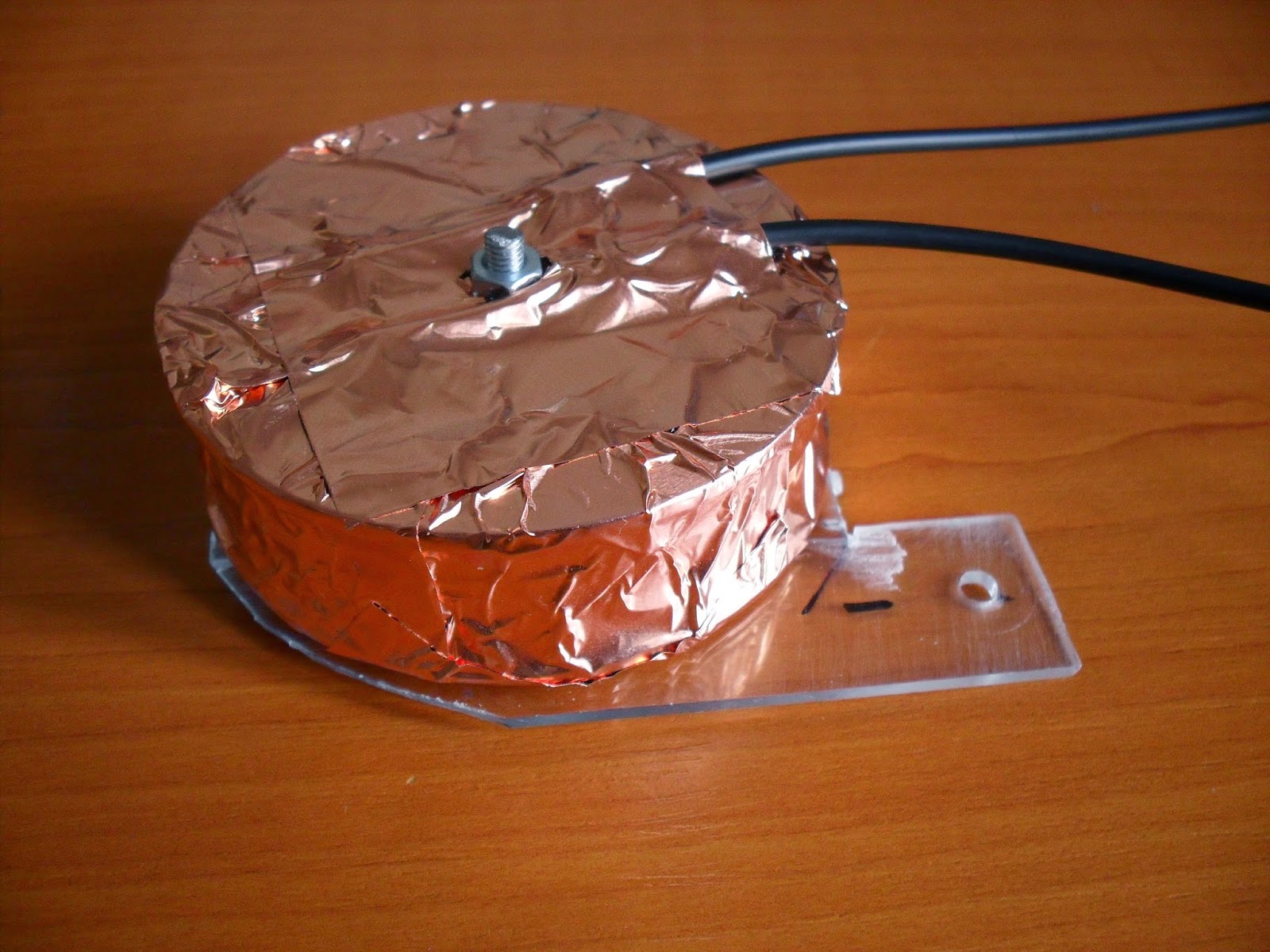
Dummy coil shielded


Mounting plexiglass piece, hole in it is for a screw that holds the bridge pickup in place
Testing the hum cancellation

The dummy coil is positioned between the pickups under the pickguard

Schematic


Monday, March 9, 2015

Danelectro shielding and stuff

Hello,

in my first article on this page, I shielded my Danelectro DC59 using an aluminum foil. It was better than nothing, but it had its flaws. One of that flaw was the bad contact between a pickguard shielding and shielding in the control cavity. Then there was the issue of shielding the cavity itself, since this guitar is hollow, and you just can't reach with the tape everywhere on the insides, because in order to do that, you would need to take the body apart. And of course, the aluminum foil looks kind of cheap and not pretty. 


But then my friend wanted me to shield two if his bass guitars, and at that time I found a good deal for a copper tape on Ebay, so I bought a lot of it and shielded these bass guitars with it. It worked great so I decided to give my Danelectro the same treatment. But this would just solve the material, but not the actual flaws I mentioned earlier. Then I found an article, where the author described his original production Danelectro from the 50's, and how he wanted to make it playable again. Anyway, there was a picture that he took of the controls shielding, which was really cool looking.

Here is the article

As you can see, there is no need to shield the body itself. This pocket or enclosure that completely covers the controls is fixed to the pickguard, so everything has solid connections and it also cuts the material used and so on ... it is simply a perfect solution. Of course, this is only usable if you have the jack mounted right next to the potentiometers, if you have a reissue Danelectro with jack on the side of the body (or if you put it there), then you need to come up with a different solution.

As you can see, I removed the aluminum foil completely and put the copper tape just near the controls because there is no need to shield the entire pickguard. Next, I needed something that would form the actual enclosure around the controls, because the tape itself is very thin and would not hold shape. I decided to use cardboard (from pizza box). The pictures are quite self-explanatory here, I really documented the whole process thoroughly so you can see the steps. No rocket science there, just making a box from a piece of cardboard which I covered in the copper tape after it was finished.

Done :)


I also reworked the wires coming from the neck pickup, as you can see, I used two shielded wires (one of them has its shield connected only on the pickup side to not cause ground loops) instead of the fat stereo one, which was really inflexible and hard to work with inside the cavity (yes I accidentally switched the green and black wire, because I'm used to the standard "black is ground" coloring).


So that covers the shielding. But there was another quite important thing I did to this guitar. As you can see in the pictures, I added a new selector switch. On the next picture, there is an original switch (the chrome one), which was very noisy, there was cracking sound when selecting and overall it wasn't very comfortable to use. I bought a similar one (the black one), but it was way worse.


The idea for this particular switch also came from my friend's bass guitar, which had this one and it was super comfortable to switch and also it is very simple and easy to work with. The bass is a Jolana D-bass, a Czechoslovakian made bass guitar that strongly resembles the Rickenbacker bass guitar. It is basically a Les Paul switch which has its bowels bent 90°. After some research, I found that this is a standard switch on the Jazzmaster guitars, so I was ready to buy it. Of course, there is always a catch, and with this switch, it's a big one.

The standard Danelectro switch is an ON/OFF/ON configuration, meaning that the pins are connected to nothing when in middle position and then in the outer position the middle pin and one of the outer pins are connected. The standard Les Paul switch is ON/ON/ON configuration, the outer positions function the same, but in the middle position all the pins are connected to each other. And this type of configuration is impossible to use when you want your middle position to be both pickups in series and one pickup alone in the outer positions. The Les Paul configuration (which is just me saying it is a "parallel in middle" configuration) is shown in the next pictures. As you can see, the switch is mechanically very simple, the plastic thing connected to the knob just moves the outer steel sheets away from the inner ones and breaking contact.


When I was searching for this Jazzmaster switch, I looked if they have it on StewMac, and they did (I bought it on Ebay eventually, this was just me looking for more information). And also, someone in the comments section for this product said, that it is possible to modify it for series pickup configuration by just taking it apart and change the place of the sheets. It is kind of not easy to explain in words, so I'll just post more pictures.

Switch dismantled

As you can see, the switch is very simple. In order to make it work like I wanted to, I needed to use longer screws, because I will be adding new layers (steel washers) to make space for the new configuration. But there is some plastic insulating cover on the screws that also hold the layers properly. The screws are M3, the holes are something over 4mm in diameter (it fits M4 screws, but they are somewhat loose).


So I took longer M3 screws, and tried to make them thick enough to tightly fit the layers. At first, I just used an electrical tape as shown in the picture above (the new ones are on the left, steel washers that will be used as another layers also shown). But the tape was impossible to fit, because when it was tight, it tended to curl up, and when I removed some of it, it was loose. So I used heatshrink tubing on the screws, two layers which made exactly the right diameter. Unfortunately I don't have a picture of that. Here is the modified switch finished, as you can see, it makes connection in the outer positions instead of breaking it.


Oh and I got rid of the piezo pickup, which I didn't like anyway, it picks everything you do with the guitar, every touch, every scratch since it's hollow. And the sound was rather meh.

And here is the Danelectro in its full glory :) Very nice guitar. When I bought it, there was a sticker on the head which said "totally shielded". Well it was far from it, but now it finally is. With a new smooth and comfortable switch.


Thursday, October 9, 2014

Do you even electronics?

Hi,

in this post, I will not talk about any electronic or guitar project, but I want to say something about the necessity to learn basic electronic principles, if you are new to electronics.

But first something about me. My only electronics background comes from a physics class in high school, where we learned basic principles like Ohm's law and so on. I always messed around with soldering iron and other tools as a kid, so I'm quite capable of putting some stuff together. But do I really know how it works? Or why it doesn't? Well ... no.

There really are so many schematics on the internet which are more or less tested and you can build them with absolutely no experience whatsoever. You can build amazing guitar effects with absolutely no idea what an op-amp is, or how a tube works. Just build a circuit you find and hope it works (or you can even buy some kits, which I really don't like to be honest)

But I always wanted to build some guitar effects and really understand them, to be able to hear a sound and say "ah! bigger capacitor there and a smaller resistor here" to make the exact sound that I wanted. Or understand the limitations of certain circuits, to know whether it's even possible to achieve the sound I want with what I built. And I don't think it's just me, when you build a circuit, you really don't care how it works, you are simply amazed that it works and that you made it. When I built the Condor cab simulator from runoffgroove.com, I played it for days before I started to notice, or rather started to want to notice, its limitations and flaws. But then some other schematics popped-up and so I abandoned it because "yaaay let's build something new!".

So I really encourage everyone to learn how audio circuits work, especially if you think you don't need to, because there are tested schematics around. Even if everything you built works flawlessly, there will be something that won't. And sometimes it's just a really simple thing to do to correct it. Or there is something that works, but may work (sound) better with just a small adjustments. Or you can even design you own circuit, which should be quite an achievement if you were only building someone else's schematics for now.

Ways to learn all this stuff are endless. I for example just enrolled in an online course on coursera.org called Introduction to electronics. But as always, Youtube is a fine source for everything.

Sunday, September 14, 2014

Piezo pickup preamplifier

Hi,

in this post, I'm going to talk about my piezo preamplifier. As I mentioned in the previous post, the whole idea for a piezo pickup came from a video on Youtube (LINK).  In this video, you can find a schematic for this preamplifier circuit, so I won't post it in here (not even sure if I can). Instead of a MPF102 transistor, I used BF245C, simply because I had those at home. No other changes were made to the preamp circuit.

Now lets talk about how I decided to wire the piezo pickup from the guitar. The idea was simple - to not make any, or at least very small, alterations to the actual guitar. So with my Danelectro, I only did two things - drilled a small hole from the bridge recess to the insides for pickup wires, and replaced the original mono jack with a stereo one. Nothing more, except for the actual piezo installation of course.

So the preamplifier, along with other controls, like pickup switch and a volume control, needs to be in some external box or a pedal. I decided to use a box that would hang from the guitar strap, just like for example wireless transmitter boxes.
Picture 1 - Complete circuit. (first version)
Picture 2 - Detail of the preamp board.
In the first picture, you can see the first version of this preamplifier, used in those experiments with just one piezo disc placed on various parts of the guitar body. It still has mono jacks on both ends, no potentiometer for volume control. Revised schematic is in picture 3. As you can see, the switch in one position puts through the magnetic pickup, kills power to the preamp and disconnects its output, the other position does the opposite, obviously.
Picture 3 - Final version of the schematic.
Now for the enclosure. I didn't have any guitar effect enclosure, or any other plastic or metal box ready for this project, but I had a pack of cigarettes and a steel sheet. And as it happens, 9V battery exactly fits in a pack of cigarettes. In the picture 4, there is sort of a steel frame for the box, because obviously just the paper cigarette box wouldn't last very long, so it is "reinforced" like this. The frame is made from two larger sheets forming the top and the bottom and a bent pieces that hold these two sheets together and form the actual space between them. All pieces are glued together using epoxy.
Picture 4 - Steel frame.

Picture 5 - Steel frame, switch yet to be glued to it.
The cigarette box needed to be unwrapped in order to fit the steel frame inside, and while it was like that, I taped a tin foil inside of it, just so it would be shielded a little better, it's probably not necessary because the steel frame should do the shielding quite well.
Picture 6 - Box already with holes for the jacks and control parts
Picture 7 - Top sheet added.
The whole gadget was tested before each important part, because after the addition of the top sheet, it was impossible to do any modifications or repairs. I also made a short stereo cable, simply because this is a DIY blog and also because my local audio stores didn't have any short stereo cables that look any good.
Picture 8 - Home-made stereo cable
After all that, there was just one thing to do - put it all together. So that's it :) It was a nice little project, not very hard. I still need to make something to hold it on the guitar strap, so far I used plastic cable ties as a temporary solution, but will probably use some velcro straps.
Picture 9 - Finished box
Picture 10 - Finished box, battery fits inside very well
Picture 11 - Finished box

Saturday, September 13, 2014

Danelectro piezo pickup

Hi,

in this post, I will talk about installing a piezo pickup on my Danelectro DC59. I always kind of wanted a piezo pickup on any of my electric guitars. I noticed that there are bridges with piezo saddles on the market, for Les Pauls and probably for other guitars. But those are not cheap, they're not incredibly expensive, but at the time, I did not want to invest in it.

But now that I got into DIY, things have changed. I came across a video on Youtube (here is a LINK), it explains what a piezo is and how to use it as a contact microphone. It also comes with a schematic for a preamplifier, which I'll show you in another post.

So I decided to build myself a piezo contact microphone and use it on my electric guitars. I bought a medium-sized piezo disc, which I wired as shown in the video above. I placed it on the body of my Danelectro, near the bridge. The sound was garbage and it amplified a lot of unwanted things like me touching the guitar (which was obvious). I tried the same thing with my Les Paul with similar results. Then I tried to place the disc on the headstock, just like you would do with some tuners. Results with the Danelectro were again garbage, but with Les Paul, the sound was actually awesome. But having a piezo disc on your headstock with cables going from it is not exactly pretty. And it still picked up a lot of unwanted sounds.

Then it was obvious that it would have to be placed directly on the bridge. I decided to try it with Danelectro first, because its bridge is a Badass wraparound, with very nice place on the bottom for something like a piezo membrane. Unfortunately, I didn't take a photo of the bridge before placing the piezos inside, but you can google it with ease.

I bought a few piezo discs. It's a thin metal disc, 31mm in diameter, with 18mm of the actual crystal in the center of it. When buying these, watch for these diameters, vendors in my country only show the metal disc diameter, which is kind of useless if you want to cut these metal discs away, like me. For example these 31mm discs have the same sized crystals like the 27mm ones, but those 31s were cheaper for some reason, so I didn't really care.

Then I proceeded to cut these discs to shape, I used three, one was cut on four sides into a rectangle and the other two were cut on three sides, so that there would be that metal overhang on both sides, for soldering a ground wire (which is not really necessary on both sides, but it looks better when it is symmetric, and since the bridge itself is grounded, there is really no need for an extra ground wire coming from the discs). Again, I don't have a photo of the whole pickup before it was put on the bridge, so at least I made this picture:

Picture 1 - Red lines are cuts to make the outer pieces, with the green one to make the center piece, blue and black dots are solder joints.
Be careful when cutting the disc, the ceramic middle is very fragile. I used regular tin snips without trouble. Also soldering the middle is kind of tricky as it can easily melt away if you heat it too much, the soldering iron must be in contact with it for only one or two seconds. There are many posts or videos on the internet about soldering piezo disc so look those up.

When the threes discs were shaped and wires soldered to them, I used epoxy to glue it to the bridge.

Picture 2 - Whole pickup is being held in place while the epoxy hardens.
Picture 3 - Pickup is finished.


In the third picture, there is a finished pickup, but it wouldn't work like this, because as I found out, the strings are touching the pickup (cutting through epoxy) and therefore shorting it out. So I covered it with a tape (picture 4). It worked for a few hours, then the strings cut through the tape. As you can see in picture 5, I put a piece of metal beneath the strings in place where they shorted the discs, so the pressure from the strings is more divided on much bigger area.

Picture 4 - Pickup covered with tape.
Picture 5 - Thin piece of metal to prevent shorting.

Picture 6 - Tiny hole drilled for the piezo pickup wires.
The piezo hot wire is wired to a stereo output jack (the middle part of the jack, tip is still the hot output from magnetic pickups, sleeve is a common ground for both pickups) which replaced the original mono jack on the guitar. When a mono instrument cable is connected, the piezo pickup is shorted out. More on that in the post about the preamplifier used with this.

Also while the guitar was dismantled, I thought it would be a good idea to shield it better (it was not shielded at all - loud hum). It's usually done with copper tape, but I didn't have it and it's very expensive. Tin foil is a good replacement, secured in place with double-sided tape. In the pictures, it looks very crappy, because it was not easy to place it inside the guitar, but it works like a charm anyway, so that is good enough for me. I also replaced the pickup wires with shielded microphone cables (they are not the same because of the way the Danelectro is wired, the thicker one is stereo, thinner one mono - it looks little bit silly, but I had those cables lying around so why not use them).
Picture 7
Picture 8 - Pickguard shielded
Picture 9 - Insides of the guitar shielded - not pretty, but works flawlessly. The pickup hole and that bridge recess kind of looks like a face doesn't it? :/
Picture 10 - Pickup wires replaced by shielded microphone cables, solder joints near the pickups covered with tin foil and tape for maximum shielding.

So that's it, I hope someone will find this helpful :)

Oh and it wouldn't be complete without a sound sample, so here it is, just a quick recording to give you an idea on how the sound changes from regular magnetic pickups, as you can hear, it's not exactly an acoustic guitar sound, so I'm thinking of building one of those acoustic simulators for it. Recorded using a Fender Mustang.

LINK to Youtube